


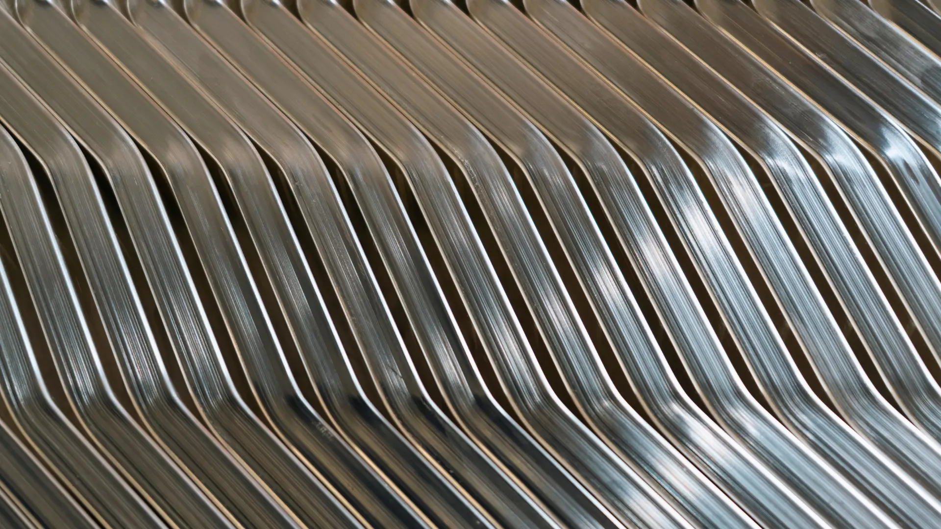

Busbar manufacturing is a multi-step industrial workflow that turns raw conductive metal, usually copper or aluminium, into metallic strips and bars that serve as precision electrical conductors.
This article looks at the main stages involved in producing a busbar, from material selection and fabrication to surface treatment and inspection.
From raw material to busbar
Busbars start as raw materials, which are extracted and put through the manufacturing process before the conductors can be delivered, installed and used on site.
The stages and processes vary depending on the busbar manufacturer or supplier; sometimes the material may have been cast, rolled or extruded earlier in the supply chain before it reaches the busbar fabricator. It can also involve melting and shaping materials into bars using a wide range of methods. Cleanliness is important here to ensure that contaminants such as dust and dirt are kept out and that air and gases do not form bubbles.
Material selection
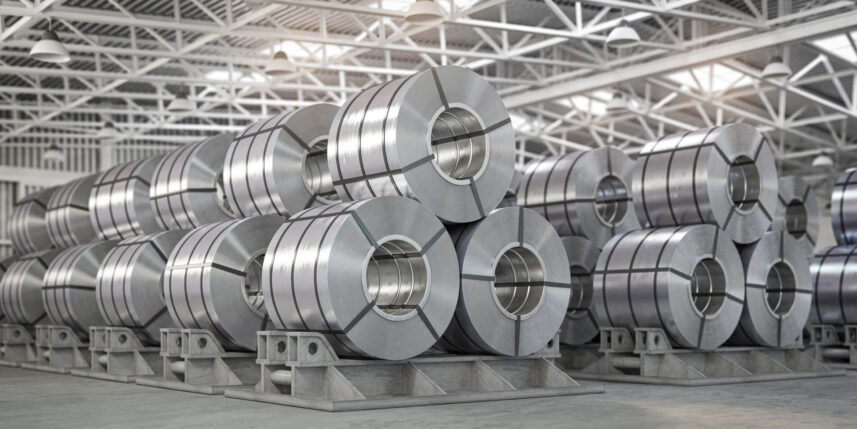
Copper has traditionally been one of the main materials used for busbars, as it possesses high electrical conductivity, durability, mechanical strength and a long service life. However, aluminium is increasingly being used in some applications because it is lighter, making it advantageous where larger conductor sizes, material cost and lower weight are considerations.
Other metals can be used for specialist components, although they are less common for high-current busbars. Examples of this include brass or stainless steel, which can be used where the bar acts as a stamped contact carrier or terminal interface rather than as the main current-carrying conductor.
Material selection also involves considering which grade of aluminium or copper is suitable, from oxygen-free copper to EC-grade aluminium. Other factors to be considered are temper, dimensions and conductivity. Most importantly, the chosen material must be suitable for the application.
Fabrication
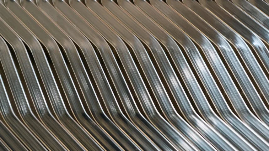
Busbars are typically flat metal strips, so once the stock has been selected, it has to be fabricated and formed to meet the required drawing and customer specification.
After the raw material has been processed and shaped, the next stage involves cutting, bending, forming, shaping and punching the busbars. A wide range of methods is used:
- Cutting to length
- Punching holes and slots
- Drilling
- CNC machining
- Sawing or shearing
- Bending and forming
- Threading or fitting inserts
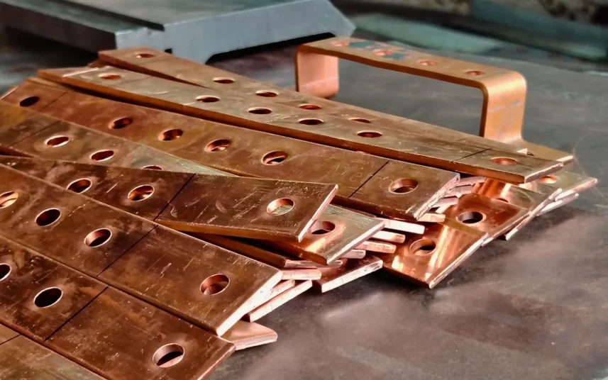
Deburring is also used to get rid of any sharp edges that might affect the performance of the busbar and to make the bars safe to handle. The application and customer requirements are also important here, as the busbars have to be cut to size.
Laser cutting and waterjet cutting may also be suitable for certain designs, materials and thicknesses. The process needs to be selected carefully to take into account where the finished part includes critical contact faces or tight tolerances.
Insulation and lamination
Busbars can also be laminated or insulated, including with dielectric insulation. Some outdoor busbars can be anodised or powder-coated. This may include heat-shrink sleeving, powder coating, moulded insulation, epoxy coating or laminated dielectric films. You can find more information here about electroplating or powder coating busbars.
Surface treatments
Sometimes we think plating just makes a busbar look nice, but even though the coating is only microns thick, it does more than improve its appearance. Busbars can often operate in a wide range of industrial conditions where humidity, chemical contamination, temperature cycling and contact with dissimilar metals occur.
These conditions make them prone to oxidation, galvanic corrosion and rust, which can spread from the joints to the whole bar over time. Whilst maintenance is a viable option, access can be difficult in some applications, making routine maintenance expensive and difficult to undertake. Correctly specified protective coatings help protect the bar and extend its life, keeping resistance low and the busbars in good condition.
Selecting the right finish is just as important, as there is more than one electroplating system for busbars:
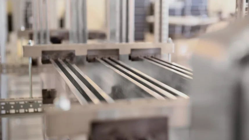
Your technical specification will guide you on which plating system to use for your busbars, as the different plating processes offer different benefits. For example, silver offers high conductivity and low contact resistance; nickel provides hardness and wear resistance and is used for high-temperature applications; tin offers corrosion resistance and solderability; and copper plating offers high conductivity and corrosion resistance. As a general guide, it is important to consider what your application needs to do and the environment in which it will operate. Tin may be unsuitable for high temperatures because of its low melting point, or you may need nickel for applications involving many interfaces, mating components and sliding components.
Some of these plating systems can be combined; for example, some busbars have a nickel barrier layer beneath another plating system and some aluminium busbars can have a copper undercoat for adhesion and conductivity, as well as a plating layer on top to protect against oxidation and tarnish. The right system depends on the application, operating environment, temperature, joint design and mating materials.
Find out more about why busbars need surface treatment.
Quality tests
As the last step, the busbars can be tested for quality and electrical performance, and inspected to check that they meet the required specifications or standards. They are inspected and tested against the customer drawing, material specification and applicable product or assembly standard.

Other checks can include:
- Burrs, edge condition and visual finish
- Compliance with restricted-substance requirements, including RoHS where applicable
- Contact resistance at joints or interfaces
- Dimensions, flatness and hole positions
- Insulation integrity and dielectric withstand performance for insulated assemblies
- Material grade and conductivity or resistivity
- Plating thickness, coverage and adhesion where applicable
- Temperature-rise verification where required
For example, IEC 61439 is relevant to low-voltage switchgear and controlgear assemblies, while UL requirements may apply to products supplied into North American markets.